海外の自作仲間からMulti-Band VFOをキーパッド対応にしてほしいという依頼があった。最近のSNSのお陰で、世界中の無線家と繋がることが出来るようになった。無線で繋がり、インターネットで繋がり、情報交換が出来る時代なのだとつくづく感じる。
マルチバンド対応VFOともなると操作のためのスイッチ等が増加し、前回のVer3ではI/Oの不足からアナログ入力を使用してスイッチを増やした。今回キーパッドともなると一挙にスイッチが増えることと、前回まででArduino-nanoのメモリーも限界に近く、これ以上の機能増加は無理である。
そこで今回はArduino-mega2560を使用することとした。megaであれば、I/Oもメモリーも十分すぎるほど増える。逆にもっと機能を増やしてみたくなる。とはいえまだArduinoを始めて半年あまりなので、まだよく理解できていないことから、キーパッドによる操作のみの改良とした。今後アイデアが出てきたら機能アップをしていきたいと思う。
キーパッドはごく一般的な4x4の16キーのものを使用している。制御線は4x2=8本を使用している。このキーパッドもご他聞に漏れずライブラリーが用意されている。こういうところがArduinoの良いところであろう。難なく制御が出来た。
逆に今まで使用してきたロータリーエンコーダーがうまく動作しない。これはハードウェアPin割り込みがUNO,nano等とCPUの違いにより動作が旨くいかないようである。暫く検討したが、私の知識では解決できなかった。そこで、JA2GQPさんにHELPしたところ、ばっちり動作するようライブラリーを改造してくれた。誠にうれしい限りである。
キーパッドでは、テンキーと付属機能用のスイッチを割り付けている。テンキーでは、バンドを直接呼び出すダイレクトキーとして、又周波数直接入力時のテンキーとしての2つの機能を持たせている。各スイッチの機能を以下に示す。
 |
| Input frequency dirctly |
- テンキー(1-9,0)
バンドを直接選択。押せばそのバンドに移行する。移行前の周波数情報などはROMに記憶し、次回はこの周波数で呼び出される。GEN(0)キーは、ゼネラルバンドとして450KHzから30MHzまでのゼネラルカバーとしている。これによりMWからHFまで使用できるようにした。ただしこのバンドの時は受信専用で送信できないような措置を行っている。
またENTキーを押した後は、周波数を直接入力するテンキーとなる。
- STEP エンコーダーの周波数ステップを変更(10Hz,100Hz,1KHz,10KHz)
- MODE
電波形式を変更する。LSB,USB,CW,AMと変更され、VFO周波数のシフトも行う。尚、モード情報はI/Oの(38,39)にバイナリーで出力しているので、キャリア周波数変更等に使用できる。
- MEMO
メモリー機能は、今のところあまり活躍していないが、電源を切るときに現状情報を記憶し次回ONしたときに同じ周波数、モード、ステップで立ち上がる。
- RIT
Ver.3と同じで受信専用で±10KHz可変可能
- ENT
ENTキーを押すと周波数直接入力モードになり、画面上に( F: )が現れ、テンキーで周波数を打ち込むとここに表示される。尚、入力できるのは、現在のバンドの上限下限の範囲内としている。自動的にバンドを設定するようにはしていないので、入力したいバンドに先に移動しておく必要がある。周波数を入力後再度このキーを押すことにより切り替わる。
- CLR
周波数直接入力を行っているとき、入力ミスをしたときにクリアーする。
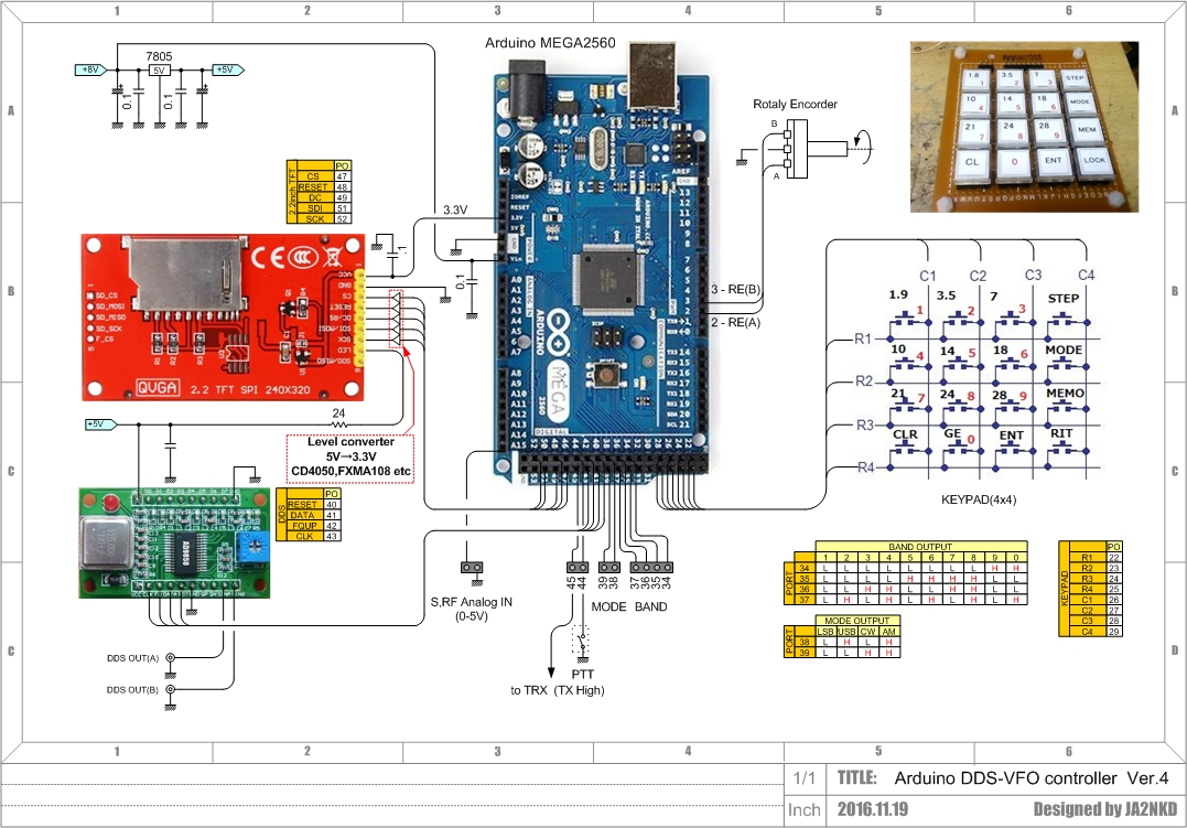
I/Oの機能を以下に示す。
- PTT(44,45)
44pinをLowにすることにより送信状態となり、画面上に「ON AIR」と表示する。送信時は45pinがHighに替わり、送受信回路を切替制御できるようにしている。
- MODE(38,39)
モードによりこの2pinにバイナリーで情報を出力している。これでフィルタやキャリアの切替を行うことが出来る。(回路図参照)
- BAND(34,35,36,37)
選択されたバンド情報をバイナリーで出力している。(回路図参照)
- メーター
Ver.3と同様でSメーターと送信パワーメーターを兼用した入力。(0-5V)
- エンコーダー(2,3)
エンコーダー入力でA相、B相入力。
- LCD(47,48,49,51,52)
2.2inch TFT液晶との接続
- DDS(40,41,42,43)
AD9850DDSと接続。尚、AD9851にも対応できるが、ライブラリーの一部修正が必要。
次にソフトウェアであるが、
スケッチと回路図は、小生のダウンロードサイトにUPしてある。
- 必要なライブラリーをそろえる。
LCD用ライブラリー
* "Ucglib.h" https://github.com/olikraus/ucglib
- AD9850用ライブラリー
* http://elecfreaks.com/store/download/datasheet/breakout/DDS/EF_AD9850_library.zip
- キーパッド用ライブラリー
* http://playground.arduino.cc/Code/Keypad
- エンコーダー用ライブラリー
* https://sites.google.com/site/ja2gqp/home/Rotary2560.h?attredirects=0&d=1
上記ライブラリーを入手したらIDEに登録を行う。尚、エンコーダー用ライブラリーはメインのスケッチと同じフォルダーに保存する必要があるので注意されたし。
IDEでバンド情報書き込み用スケッチ「VFO_V4_eep.ico」を開きmega2560に書き込む。
IDEでメインスケッチ「NKDVFO22_Ver4_001.ico」を開きmega2560に書き込む。
この手順で書き込まないと旨くいかない。
回路図
A keypad is using 4x4 keys of 16key. A control line is using 8 lines. This key pad library is prepared. With no trouble I could control.
The rotary encoder used so far conversely doesn't move well. Hardware Pin_interrupt is UNO,nano and mega, movement is better and they don't seem to go to be different. It was considered for a while, but it couldn't be settled by my knowledge. JA2GQP He made me encorder ribrally for mega2560. Very thanks.
Keypad is allothed a numerical keypad and the switch of functions
Numerical keypad (1-9,0)
A band is chosen directly. When pushing it, shift to the band. Frequency information before a shift memorizes in ROM and is called by this frequency next time. The GEN (0) key is made a general band from 450KHz to 30MHz. You can use from MW to HF. But only receiving.
After pressing a [ENT] key, it'll be the numerical keypad which inputs a frequency directly.
STEP
The frequency step of encoder is changed (10Hz,100Hz,1KHz,10KHz).
MODE
It's changed with LSB,USB,CW,AM, and a VFO frequency is shifted. Mode information is output binary to I/O(38,39), so it can be used for carrier frequency change.
MEMO
When you push {MEMO] then memorizing the current state information and turning on next time started by the same frequency, mode and step.
RIT
It's same as Ver.3 +/-10KHz variable possible
ENT
When a ENT key is pressed, it'll be a frequency direct entries mode, and when [ F: ] appears on the screen, and a frequency is driven in by a numerical keypad, it's indicated here. It's necessary to move to the band you'd like to input first. choose a frequency as pressing this key once again after input and switch over.
CLR
When doing a frequency direct entries, when doing an input mistake, it's cleared.
The function of the I/O is indicated below.
PTT (44,45)
It'll be transmit mode by making 44pin Low, and indicates "ON AIR" on the screen. When sending, 45pin change High. It can use TRX circuit and control.
MODE (38,39)
Mode information output s 2bit binaly . It's possible to change a filter and a carrier with this. (Circuit diagram referring)
BAND (34,35,36,37)
Band information output. (Circuit diagram referring)
Meter
The analog input which was like Ver.3 S-meter and transmission power meter input. (0-5V)
Encoder (2,3)
By encoder input.
LCD (47,48,49,51,52)
2.2inch Connection with TFT LCD.
DDS (40,41,42,43)
AD9850DDS connection.
Next it's software. Sketch and a circuit diagram is my download site.
Library for LCD
* "Ucglib.h"
https://github.com/olikraus/ucglib
Library for AD9850
* http://elecfreaks.com/store/download/datasheet/breakout/DDS/EF_AD9850_library.zip
Library for keypads
* http://playground.arduino.cc/Code/Keypad
Library for rotaly encoders
*
https://sites.google.com/site/ja2gqp/home/Rotary2560.h? attredirects=0&d=1
This library is necessary in the same folder as a main sketch, so please be careful.
If get the above library, it's register with IDE except .
A sketch for band information writing in "VFO_V4_eep.ico" write in mega2560.
Main sketch "NKDVFO22_Ver4_001.ico" writes in mega2560.
73's